CRB
Below we have answered frequently asked questions from our customers specific for the controller CRB. If you do not find your answers here please contact your closest wholesaler or ESBE Sales company in your country.
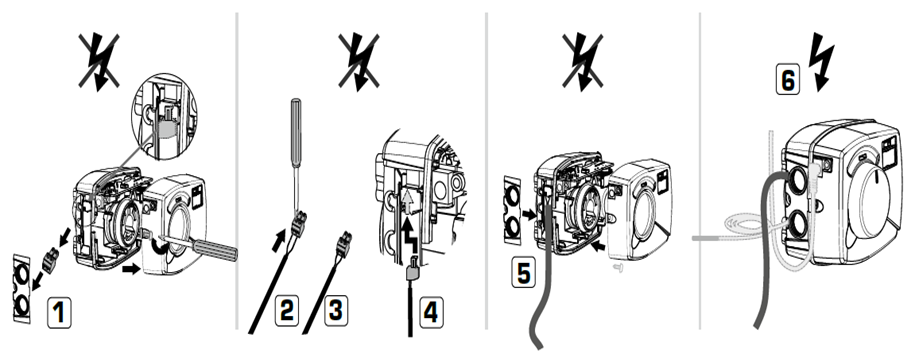
How is the opening direction changed on the CRA110 and CRB100?
The rotating direction is changed in the following order:
- Remove the power
- Push and hold the joystick to the same directions as the valve will go from closed to open
- Connect the power again and keep to hold the joystick a couple of seconds
- The working direction is now changed
How is the room temperature changed on the controller series CRB100 or CUA100?
The set room temperature is changed in the following order:
- Press the knob shortly on the room unit
- Increase or decreas the temperature by moving the knob to the right or left
- Confirm by pressing the knob shortly
How is the maximum supply temperature changed on the series CRB100 or CUA100 controller?
The settings are changed in the following order:
- Press down the knob for 4 seconds on the room unit
- The wrench and the "MAX" symbol will be shown
- Press the knob shortly and the numbers will be flashing
- Change the temperature by moving the knob to the right to increase the temperature and to left to decrease the temperature
- Confirm by pressing shortly on the knob
- Press down the joystick for 4 seconds or wait 20 seconds to return to main menu
How is the minimum supply temperature changed on the series CRB100 or CUA100 controller?
The settings are changed in the following order:
- Press down the knob for 4 seconds on the room unit
- The wrench and the "MAX" symbol will be shown
- Turn the knob to the left
- The wrench and the "MIN" symbol will be shown
- Press the knob shortly and the numbers will be flashing
- Change the temperature by moving the knob to the right to increase the temperature and to left to decrease the temperature
- Confirm by pressing shortly on the knob
- Press down the joystick for 4 seconds or wait 20 seconds to return to main menu
What temperature is the room unit display showing and what temperature is the controller unit display showing on the CRB100 or CUA100 controller?
The room unit display shows the real room temperature (Note: if C=0, please see FAQ answer regarding C=0 and C=1) and the controller unit display shows the real supply temperature.
What is the difference between the C=0 and C=1 on the CRB100 or CUA100 controller?
In the same menu as settings are made for Maximum supply temperature and Minimum supply temperatur there is a possibility to set the C settings. C settings is to decide what version of controller function the controller has. The different avialable settings are the following:
C=0 This is indoor temperatur based controller function. The display will show the actual room temperatur and if you press the know shortly you will see the desired room temperature
C=1 This is constant supply temperatur controller, with this setting is the room unit just a remote control for the controller unit. The display will show the actual supply temperatur and if you press the know shortly you will see the desired supply temperature.
What does the arrows in the display of the CRB100 or CUA100 describe?
The arrows shows how the real temperature is according to the set temperature. For example if the arrow is pointing up it means that the real temperature is below the set temperature. If the arrows is flashing is it indication that the valve is fully closed/open and the controller can't do more to archive the target temperature.
How do you know if the wireless communication works in the series CRB100 or CUA100 controllers?
If the radio symbol is steady and not flashing means that there is a working communciation between the room unit and the controller unit. If the radio symbol is flashing it means that the radio communication is not working. If so, please change the position of the room unit to a better place. Please try to avoid steel and water in the thinking path between the room unit and the controller unit.
How long can the distance be between the wireless room unit and the controller series CRB120 unit be?
Depending on the circumstances, the transmission range between room unit and controller unit inside a building can be anything from 60 to 20 meter depending on orientation of the products and material used in the building.
Some kind of materials might attenuate the radio waves more than other. Here are some examples on attenuation from litterature:
Wood, gypsum board, glass pan 5-10%
Brick walls 10-40%
Concrete with arming 10-90%
Metal 90-100%
Some kind of materials might stop the radio communication totally. Some examples are metal sheets and water. A typical source of problem is when the transmission has to pass the boiler or an accumulator tank. Those subjects might block the transmission fully.
On the other hand the radio waves might reflect in the surface of such a subject as an accumulator tank so a good communication is achieved.
A good advice is to test different places for the room unit. Also small movements might dramatically change the signal quality. It’s also a good idea to test different orientations of the controller unit.
For what can the auxiliary switch in the series CRB100 be used?
The auxiliary switch can be used to connect external equipment that you would like to start/stop by the valve position. Example can be circulation pump that you would like to turn of if the valve is closed. Another example can be auxiliary heat that you would like to turn on when the valve reach a specific valve postion
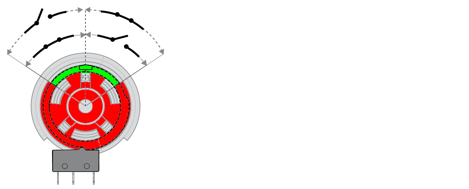
How do you adjust when the auxiliary switch in the series CRB100 shall be activated or not?
Under the knob on the controller unit is a green adjusting cam. By moving this green cam are you changing when the auxiliary switch will be activated/deactivated.
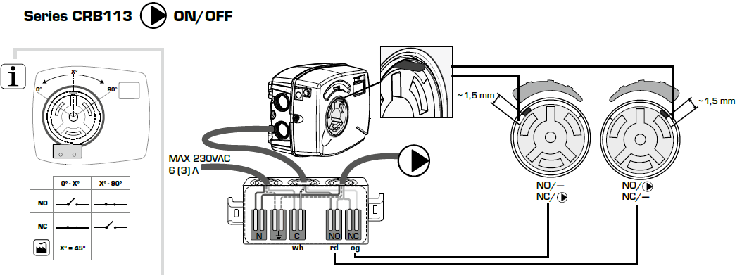
How is a circulation pump connected to the auxiliary switch on the controller CRB113 or CRB114?
Please see picture attached
How can T2 be activated by external equipment to the controller series CRA100 or CRB100?
Under the cover of the controller unit is a green connector. On this connector you connect two wires and when the two wires are connected together the T2 temperature is activated. Example of external equipment is the ESBE GSM-module CRB915 (art nr 1705 59 00) where you can swift between the two preset temperature by your cellphone.
NOTE: The signal from the external eqipment must be without any voltage or resistance.